
Instrument Expert
Original factory packaging

Service Hotline:
(+86)010-52867771
Instrument Expert
Original factory packaging
Service Hotline:
(+86)010-52867771
Updated:2025-03-13
Views:2043
 WeChat
 QQ
QQ
 Online Service
 User's Manual
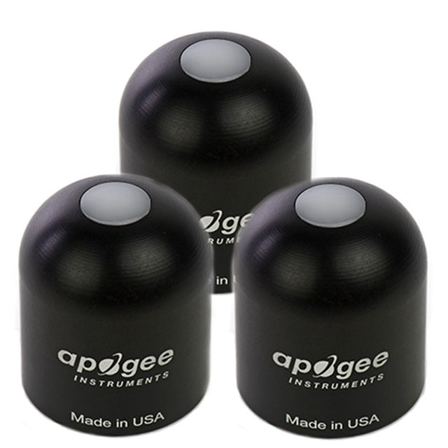
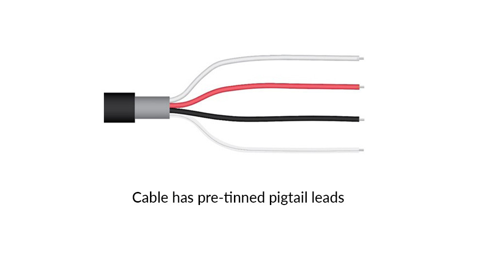
Apogee model SP-214 pyranometers provide a 4-20 mA output that is proportional to incident total shortwave radiation. A quick and easy check of sensor functionality can be determined using a DC power supply and an ammeter. Power the sensor with a DC voltage by connecting the positive voltage signal to the red wire from the sensor and the negative (or common) to the black wire from the sensor. Use the ammeter to measure across the white wire (signal output) and black wire (signal ground). Direct the sensor head toward a light source and verify the sensor provides a signal. Increase and decrease the distance from the sensor head to the light source to verify that the signal changes proportionally (decreasing signal with increasing distance and increasing signal with decreasing distance). Blocking all radiation from the sensor should force the sensor signal to 4 mA
The 4-20 mA circuit design allows the output to drive a resistive load (RL) to within 2 volts of the supply voltage to the sensor (VS), at 20 mA (0.02 A). The equation to calculate resistive load is RL = [VS – 2 V] / 0.02 A. For example, a sensor with a supply voltage of 12 V DC can drive a maximum load of 500 Ω (RL = [12 V – 2 V] / 0.02 A = 500 Ω). The output voltage from the sensor is calculated by adding the wire resistance to the input resistance of the data collection system, and then multiplying by 0.02 A.
 alt="" />
| ISO 9060:2018 | Class C (fast response) |
| Power Supply | 7 to 24 V DC |
| Current Draw | 22 mA maximum; 2 mA quiescent |
| Sensitivity | 0.008 mA per W mˉ2 |
| Calibration Factor | 125 W mˉ2 per mA (reciprocal of sensitivity) with an offset of 4 mA |
| Calibration Uncertainty at 1000 W mˉ2 | Less than 3 % |
| Calibrated Output Range | 4 to 20 mA |
| Measurement Repeatability | Less than 1 % |
| Non-stability (Long-term Drift) | Less than 2 % per year |
| Non-linearity | Less than 1 % (up to 2000 W mˉ2, maximum radiation measurement is 2000 W mˉ2) |
| Response Time | Less than 1 ms |
| Field of View | 180° |
| Spectral Range | 360 to 1120 nm (wavelengths where response is 10 % of maximum) |
| Directional (Cosine) Response | ± 5 % at 75? zenith angle |
| Temperature Response | 0.04 ± 0.04 % per C |
| Operating Environment | -40 to 70 C; 0 to 100 % relative humidity; can be submerged in water up to depths of 30 m |
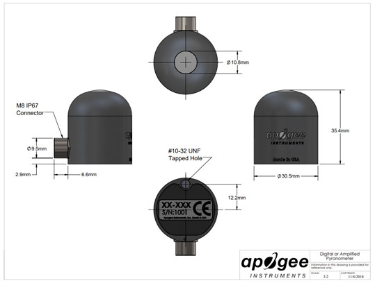
| Dimensions | 30.5 mm diameter, 37 mm height |
| Cable | 5 m of shielded, twisted-pair wire with TPR jacket (high water resistance, high UV stability, flexibility in cold conditions), additional cable available |
| Mass (with 5 m of cable) | 140 g |
| Warranty | 4 years against defects in materials and workmanship |
| Manufactured | Made in the USA |
Customer Service QQ
Customer Hotline:
Technical Supports


 3003988120
 yiqi.com
 bio-equip.com
 b2bwork.baidu.com
 baidu.com