
Instrument Expert
Original factory packaging

Service Hotline:
(+86)010-52867771
Instrument Expert
Original factory packaging
Service Hotline:
(+86)010-52867771
Updated:2025-03-13
Views:1843
 WeChat
 QQ
QQ
 Online Service
 Datasheet
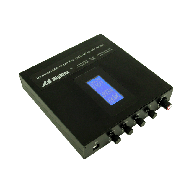
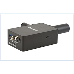
Mightex’s four-channel SLC/MU-series universal LED controllers are designed to drive a broad range of LED light sources, and they offer the flexibility for users to operate each LED channel independently, both manually and through software. In addition, the LEDs can be driven both in Continuous Wave (CW) mode and in strobe mode. The software comes with a user-friendly GUI that enables one to drive LEDs without the need to write any code. Furthermore, a full-featured SDK is provided in order for users to write their own software and to integrate the LED controllers into their own systems.
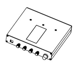
1. Manual Control: Each of the four channels can be operated manually in CW mode using a knob, and each knob is
operated independently to control the output current of a specific channel. The LED controller also has a fifth knob
(i.e. a “Global” knob) that enables one to adjust the output current of all the channels at the same time and with
the same step size. Therefore, one can first set the intensities for the LED channels – independently – using the
four (small) knobs, and then can increase/decrease the set intensities of all channels simultaneously using the
“Global” knob.
In order to prevent LED damage due to ‘overdriving/overheating’, the maximum output current of each LED channel
can be set individually, via the software provided with the LED controller, to match the current rating of the LED
connected to the channel.
2. Software Control: The LED controller can also be operated via a Windows-based application software, provided with
the device. In software control mode, each channel can be individually configured by the software to operate in one
of the following three modes:
a. Disable Mode:
The channel is disabled, and its output is completely turned off.
b. Normal Mode (or CW Mode):
The output current is constant, which can be adjusted (using software) from 0mA to 1,200mA through the USB
interface.
c. Strobe Mode:
A Pulse-Width-Modulated (or PWM) periodic strobe pattern is output from the channel, which can be activated by a
software trigger. The strobe pattern may last indefinitely or for a preset number of cycles, depending on the
software setting. The maximum frequency of the PWM strobe is 500Hz.
The LED controller also has a DC output used to control a cooling fan, usually used to cool down a high-power
LED. The LED controller’s software allows one to control the speed of the cooling fan, through a designated variable
PWM signal output.
FEATURES
Software/manual controlled
Current monitoring display
Universal driver- suitable for any LED
User friendly application software with GUI
Capable of driving variable loads
Full-featured SDK
Up to 1200mA output current
High precision with 1mA current resolution
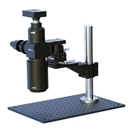
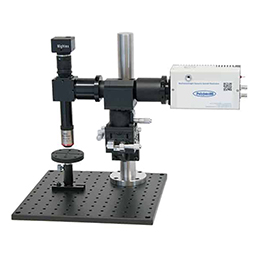
APPLICATIONS
Machine Vision
Semiconductor equipments
Displays
Test Instruments
Microscopy
Medical Instruments
| Parameters | SLC-CA04-MU | SLC-MA04-MU | Unit |
| Number of Channels | 4 | 4 | |
| Power Supply Input Voltage (Vdc ) | 12 ~ 24 | V | |
| Maximum Output Voltage (Vmax ) | Vdc - 3.0 | V | |
| Maximum Per Channel Output Current (Imax ) | 1200 | mA | |
| Maximum Per Channel Output Power (Pmax ) | 18 | W | |
| Output Current Resolution | 5 | 1 | mA |
| Output Current Accuracy | ±5 mA or ±1.0%, whichever is larger | mA | |
| Output Current Repeatability | ±2 mA or ±0.5%, whichever is larger | mA | |
| PWM Timing Resolution | 100 | μs | |
| PWM Timing Minimum Step Size | 1000 | μs | |
| Interface | USB | ||
*Note: If the channel output voltage is Vd and the output current is Id, they must simultaneously satisfy: (1) Vd <= Vmax ; (2) Id <= Imax; and (3) Vd *Id <= Pmax. Each period of a PWM square wave comprises of ON time and OFF time ( i.e. two steps). The minimum value for each step is 1,000μs, and the minimum increment is 100μs.
Customer Service QQ
Customer Hotline:
Technical Supports

 3003988120
 yiqi.com
 bio-equip.com
 b2bwork.baidu.com
 baidu.com